For most of the photos on this page, you can click the image for a larger picture.
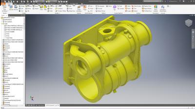 |
All the small bosses and radii are added and the 3D model is complete. |
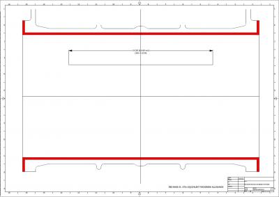 |
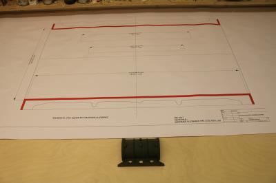
From the model, details can be extracted to help Tony create the wooden pattern, this shows the profile of the motion cylinder. Tony prints the drawing at full size and measures directly from the print. You will see this drawing in use on page 2.
Keith's drawing of the motion cylinder is important for Tony as it's now a 'pattern drawing' i.e. scaled up for shrinkage and that's how Tony can take off measurements and apply them to the pattern. This is the whole reason why Keith is doing 'pattern drawings' which changes the 'works drawing' into something the pattern maker uses to make life much easier and to all but remove a chance of error. When Tony places the half cylinder pattern on Keith's drawing which is on his bench, it will show him if errors are creeping in. Without Keith's drawings, Tony would have to painstakingly draw out these sections, adding shrinkage allowance, on white faced hardboard - this would be a real minefield for errors creeping in. |
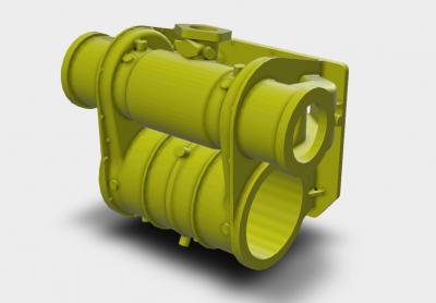 |
This is the outside view of the cylinder assembly from the CAD model. The valve cylinder/steam chest is on top and the motion cylinder is below. CAD allows you to rotate the assembly in all directions for a specific view. For the cylinders we are using Spheroidal Graphite or SG Iron with a shrink rate of 1/80. The pattern will be 1/80th larger than the finished casting to allow for this shrinkage. |
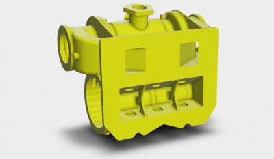 |
This is the frame side view of the cylinder assembly. The steam inlet is to the top and the exhaust steam ports can be seen coming from the outside ends of the valve cylinder onto the flange plate. These connect with the exhaust steam spider and then onto the blastpipe in the smokebox. |
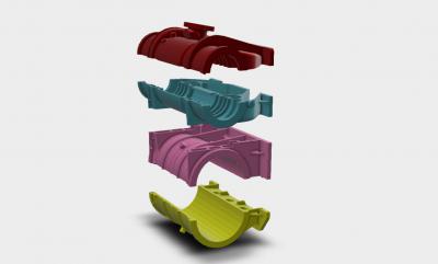 |
In order to produce a complex casting like this, the pattern must be broken up into sections so that the patterns can be lifted out of the sand mould without disturbing the mould. Tony and Keith working with Phil Yates from the Advanced Manufacturing Research Centre in Sheffield, decide how best to split the pattern. They decided that the pattern will be made in 4 sections, split horizontally as can be seen. This will allow the various pattern sections to be removed from their section of the casting mould before the complete mould is assembled. If you look carefully, you can see a small step in the plane between sections 2 and 3. This makes the pattern making just a little more complex. |
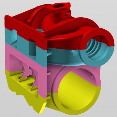 |
Put the sections together and you get a complete outside cylinder. |
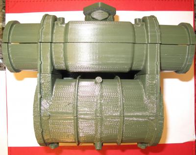 |
Phil then used a 3D printer to create this model of the patterns. This is very useful for Tony in helping visualise how the pattern will be built.
Normally, you don't see this as the cylinder is enclosed within sheet metal covers. The valve cylinder is on the top with the steam inlet at the top centre. The connecting ports between the valve cylinder and the motion cylinder can be seen clearly |
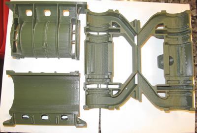 |
This is the 3D model broken into its component parts. In the bottom left is the bottom of the motion cylinder looking down from the top. The flange for bolting to the main frames is at the bottom. In the top left is the top half of the motion cylinder, again looking down from the top. Here you can see the exchange ports with reinforcing bars in the walls. The frame flange is at the top.
The middle component is the bottom half of the valve cylinder. The diagonal arms are the exhaust steam passages which will connect with the exhaust steam spider located between the frames. The view is looking down from the top of the assembly.
The final component is the top of the valve cylinder and this is upside down. The main steam inlet is in the middle. This goes off at an angle which is going to pose a tricky problem for Tony!
Tony says that "The plastic print is a really useful addition to the pattern making process and allows me to see in my hand where I have to add all sorts of removable bits and pieces to allow the Moulder at the foundry to release the pattern from the sand. When I make my first visit to the foundry, I will take Phil's plastic print and this will allow the moulder to more easily see in solid 3D what he has to do and then he will advise me as to what I need to do in pattern terms". |
 |
Now we move to Tony's workshop to start the construction of the main cylinder pattern. In the main, the cylinder is symmetrical so we only need one pattern. With some minor changes, we can use it for both left and right hand cylinders.
This is the drawing for the bottom half of the motion cylinder with the 3D model below. You can see how the shrinkage allowance was changed after the first set of drawings were issued. In British Railways days, this would have meant that the whole drawing would have had to be redrawn. In the CAD world, it's a simple matter of changing a resizing allowance and a new pattern drawing is printed. |
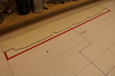 |
Tony uses the drawing to produce a template. As you can see from the photo of the final casting above, the cylinder has a couple of strengthening ribs (are they or do they support the cylinder cover?) which need to be replicated on the pattern. The template will help Tony when he's working on the lathe |


